What is UART communication? The most complete UART communication knowledge (2024 edition)
UART (Universal Asynchronous Receiver/Transmitter) is a widely used serial communication protocol employed extensively for inter-device communication in microcontrollers and various embedded systems. This article aims to provide a detailed introduction to the basic principles of UART communication, operational modes, baud rate calculations, and common usage practices, assisting individuals with some microcontroller development skills in better understanding and applying UART communication.
1. Asynchronous Communication Mechanism of UART
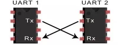
UART operates on an asynchronous serial communication method, which essentially means data is transmitted bit by bit over a data line without requiring the sender and receiver to be synchronized. The UART system consists of a transmitter and a receiver, which communicate via this data line.
The transmitter converts data to be sent from parallel to serial form through a driver circuit, which then transmits it over the data line. The receiver reconstructs these signals back from serial to parallel form, thereby retrieving the original data bits.
In asynchronous communication, the transmitter and receiver do not have to operate at the same time but communicate by marking the beginning and end of data frames with start and stop bits, respectively. This method allows the receiver to identify the start of a new data packet and successfully capture the transmitted information.
2. Baud Rate of UART
The baud rate is the number of binary data bits transmitted per second, typically measured in bps (bits per second). For instance, a baud rate of 9600 bps means that 9600 bits are transmitted each second. The baud rate for serial communication is generated by the microcontroller’s clock system, which ties it mathematically to the system clock frequency through a specific formula:
Baud rate = (16 * clock frequency) / (32 * sampling time) + (1 * clock frequency) / (32 * sampling time) .(1 * clock frequency) / (64 * sampling time)
Common baud rates are multiples of 2400 bps, such as 2400, 4800, 9600, 19200, 38400, 57600, and 115200. These rates are achievable through dividers from a base clock frequency provided to the microcontroller’s peripherals, such as a 1MHz clock.
3. Stop Bits and Parity Check
In UART communication, stop bits are used to indicate the end of a data frame, which can be one or two bits long. A single stop bit adds a bit’s worth of time after each data byte, compensating for any potential time shift caused by clock jitter. Parity bits, either even or odd, are used to check for errors in the transmission, enhancing the reliability of data transfer.
4. Polling and Interrupt-Driven Transmission
UART can transmit data byte by byte, splitting each byte into several bits. After sending a byte, the UART transmitter will generate a stop bit and then become idle, ready for the next byte. This is known as polling transmission. Alternatively, interrupt-driven transmission uses UART interrupts to handle incoming or outgoing data efficiently without continuous monitoring by the CPU.
5. Data Buffering in UART Communication
Many microcontrollers offer UART Read and Write functions, and some advanced ones provide callback functions for these operations. Data buffering, often through a queue or circular buffer, helps manage data in UART systems. This buffering allows efficient real-time data handling, ensuring no data loss occurs.
In systems where data transmission speed and efficiency are critical, hardware FIFOs (First In, First Out buffers) and Direct Memory Access (DMA) can be employed. These technologies allow for multiple bytes to be sent or received in batches, reducing the overhead on the microcontroller and increasing data throughput.
By understanding the principles, baud rate calculations, operational modes, and common practices of UART communication, developers can significantly enhance the design and functionality of microcontroller-based systems, facilitating robust and efficient serial data transmission.
Understanding these core aspects of UART communication can empower developers to better integrate and optimize this protocol in their embedded projects. Let’s delve deeper into some practical considerations and advanced features that can further enhance UART usage:
Advanced Features and Practical Considerations
6. Error Handling
While parity bits can detect errors, they don’t provide a complete solution for error correction. In practical applications, additional error handling mechanisms such as CRC (Cyclic Redundancy Check) or checksums may be implemented to ensure data integrity. These methods provide a more robust means of detecting and possibly correcting errors that occur during data transmission.
7. Flow Control
Flow control is crucial in preventing data loss when the receiver is not ready to accept more data while the sender is transmitting at high speed. There are two main types of flow control:
Hardware Flow Control: Utilizes additional lines (such as RTS/CTS) to control the flow of data directly through hardware, signaling when to pause and resume data transmission.
.Software Flow Control: Uses special control characters (XON/XOFF) sent over the same data line to control data flow. This method is simpler as it does not require additional hardware lines but can be less reliable in noisy environments.
8. Synchronous UART
Though traditionally UART is asynchronous, synchronous modes are also possible where the clock signals are shared between the sender and receiver, allowing for higher data rates and better error handling. This mode is particularly useful in environments where both ends of the communication line are controlled by the developer, allowing for precise control over timing.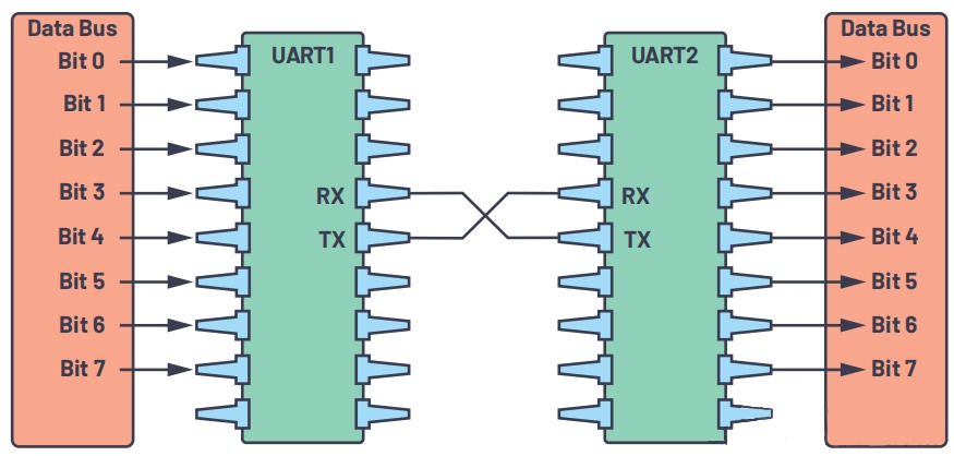
9. Multi-Processor Communication Mode
Some UART peripherals support a multi-processor communication mode, which is useful in systems where multiple processors need to communicate over a single UART bus. In this mode, each processor can be assigned a unique address, and the UART hardware can be configured to only interrupt the processor when its specific address is received.
10. Utilizing Buffers and Interrupts Efficiently
To maximize efficiency in UART communication, it’s crucial to optimize the use and configuration of buffers and interrupts:
Buffer Size: Choosing the right size for buffers can significantly impact performance. Too small buffers might lead to frequent interrupts and potential data loss, whereas too large buffers may increase latency.
.Interrupt Priority: Properly configuring interrupt priorities ensures that critical communication tasks are not delayed by less important processes. This is especially important in systems with multiple interrupt-driven tasks.
11. Power Management
In battery-operated devices, managing the power consumption of UART interfaces can contribute to extended battery life. Techniques such as disabling the UART when not in use or switching to a lower baud rate during periods of low activity can be effective.
12. Testing and Validation
Thorough testing and validation are crucial to ensuring reliable UART communication, especially in complex systems. This might include stress testing the communication under various conditions, checking for interoperability between different UART devices, and using tools like protocol analyzers to monitor and decode UART traffic.
Conclusion
UART is a versatile and widely-used communication protocol that, when implemented with careful consideration of its capabilities and limitations, can significantly enhance the communication reliability and efficiency in embedded systems. Whether through simple polling methods or advanced interrupt-driven techniques, developers have a broad toolkit to leverage UART effectively. By integrating advanced error handling, flow control, and power management strategies, the robustness and efficiency of UART communications can be maximally enhanced, paving the way for successful and scalable embedded system applications.